
The row is a pair, and the second number does the sorting
A Polaris fault row is not one fact. The component is named by the SPN — the parameter number the tables share across platforms — and the condition is named by the FMI, the number that marks what kind of failure the controller observed: voltage out of range, a circuit left open, a signal going implausible, a condition simply present. Read the pair together and a row becomes three published facts: the component, the parameter ID, and the condition. The how-to guide introduces both numbers; this guide goes one level down and shows how the condition number behaves across the tables this site publishes — 16,312 entries from 129 model-year records.
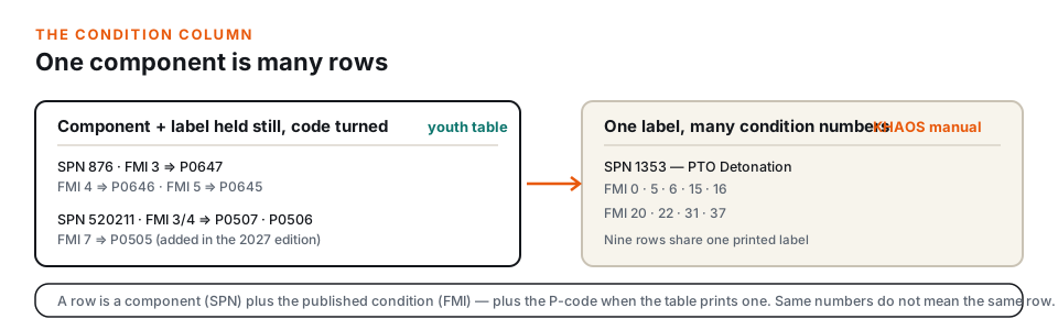
The condition number is the reason one component can occupy several rows. In the published youth table, the air-conditioning clutch relay prints three rows at SPN 876: P0647 at FMI 3, P0646 at FMI 4, and P0645 at FMI 5, all under one label. The idle-speed family does part of the same thing — P0507 and P0506 at FMI 3 and 4 on SPN 520211 ran through the whole 2021–2026 era, and the 2027 edition added P0505 at FMI 7, the one row in that family that steps off the pair. The youth table is the easiest example because it prints the P-code beside the pair, but the same structure runs through every SPN/FMI table on this site.
Ladders: the 3/4/5 trio
Across the published tables, 49 distinct SPNs print a complete FMI 3/4/5 ladder. The trio is the circuit-condition family: voltage above range at FMI 3, voltage below range at FMI 4, and the open or grounded driver at FMI 5. The tables apply it wherever a device the controller switches has to be watched — the injector rows at SPN 651 and 652, the ignition-coil drivers at 1268 and 1269, the fuel pump at 1347, the fan and chassis relays at 1071 and 520208, the all-wheel-drive control at 520207.
The printed wording varies by platform, which is exactly the kind of detail worth checking rather than assuming. The 2022 Ranger 1000 chapter labels all three rows of SPN 1347 Fuel Pump Driver Circuit — one label, three condition numbers. The Pro R family separates an injector row into per-condition wording: FMI 3 prints Cylinder 1 Injector “A” Circuit High, FMI 4 prints Circuit Low, FMI 5 prints the bare Circuit. Across the archive 452 rows carry “Voltage High” or “Voltage Low” in the label or condition text; 446 of them sit at FMI 3 or 4. The Driver Circuit phrasing appears in 1,416 condition cells and 946 component labels; 2,085 rows mention it in one or both. The low-voltage guide covers the second kind of cluster, and the diesel guide shows the same trio compressed into a 32-row table.
One habit makes the 3/4/5 band easy to read: count the rows under one component before treating any single row as the whole story. A relay that prints three rows under one label tells you the controller is watching the same circuit from three directions, and the row your display shows is one of the three, not a different fault.
The volume behind the band explains why it reads first. FMI 3 prints 3,357 published rows and FMI 4 prints 3,256 — the two largest condition families in the archive — with FMI 5 at 1,483 and FMI 2 at 1,427. The 2–5 quartet alone covers 9,523 of the 16,312 entries this site publishes, so a reader comfortable reading voltage out of range, voltage below range, and the open-circuit row can move through three-fifths of the tables with confidence.
Where FMI 31 is a condition, not a voltage
FMI 31 is the largest single condition family after the 2–5 band: 1,719 published entries, spread over 88 distinct SPNs. In the J1939 sense FMI 31 marks a fault condition detected without the specific electrical measurement the lower numbers describe — and the Polaris tables print it exactly that way. Some rows rename it plainly; some append two printed words that make its meaning unmistakable: Condition Exists.
Those appended rows sit in families where the condition is a controller judgement rather than a circuit measurement. The throttle-body control checks print Throttle Body Control - Return Spring Check Failed Condition Exists and Throttle Body Control - Adaption Aborted Condition Exists; the ECU-monitoring family prints ECU Monitoring of Injection Cut Off (Level 1) Condition Exists and (Level 2) Condition Exists, alongside ECU Monitoring Error (Level 3) Condition Exists. The accelerator/brake interaction family and the accelerator sensor-synchronicity family print their own versions of the same pattern. 45 SPNs carry an appended Condition Exists wording — 1,285 published rows in all.
Same label, different condition number
The 88-row KHAOS snowmobile manual prints PTO Detonation nine times under SPN 1353 — FMIs 0, 5, 6, 15, 16, 20, 22, 31, and 37. Never treat a bare label as the row: the condition number is the part of the citation that separates those nine rows from each other.
Other FMI 31 rows are named conditions on their own: the seat-belt switch row (SPN 1856, FMI 31, published under code B1029 in the 2027 youth table), the brake-engaged row at SPN 520555, the chassis-regulator over-voltage row at SPN 32523, and the steering rows. The steering family demonstrates how the same component moves between condition-wording families on different platforms: Steering Torque Full Failure prints at FMI 12 on the Pro R family tables and at FMI 31 everywhere else — one label, two different condition numbers by manual edition.
The FMIs beyond the textbook band
Polaris manuals print condition numbers well past the familiar 0–5 range, and several of those deserve their own reading notes because the wording does not hint at the number.
FMI 19 — received-network data. FMI 19 prints 240 published entries across 11 SPNs, and every one of them is a signal the controller reads from elsewhere on the network rather than wires it owns. Some rows say so in the label itself: Exhaust Valve Actuator Internal IC Communication Loss (the exhaust-valve actuator row on the Matryx-era snowmobile manuals) and the Pro R family's External fault, engine speed reception and External fault, vehicle speed reception. Others name the signal alone — Engine Speed, Vehicle Speed Sensor — and the condition number is what marks the message as the trouble. When a row points at received data, it belongs to the network family; see the communication guide for the tables that print those rows grouped.
FMIs 20 and 21 — implausibility checks. The Pro R family vehicles print Vehicle Speed Data – Implausible – Based on Engine Speed and Gear at FMI 20 and Vehicle Speed Data Implausible Based On Slew Rate at FMI 21. These are the controller's two agreement checks on its own speed input: one looks at what the engine and gearbox are doing, the other at how fast the reading changed. Same component, same wording family, two different tests — readable only from the condition number.
FMIs 22 and 23 — resource checks. One shared Sportsman-era manual prints Cruise Control States at both FMI 22 and 23, and the Pro R family adds Torque Request CAN Message at FMI 22 with two checksum-style rows at FMI 23: ESC 65312 checksum failure and EPS Calibration CRC error. A message that arrives corrupted or a calibration whose integrity check fails is not a wiring problem; the condition number is what separates these rows from every voltage family around them.
FMIs 36 and 37 — the regulator pair. The snowmobile manuals watch the regulator with two rows in a band almost no display shows to the owner: P1510 at FMI 36 Regulator: Stator Output Low and P1511 at FMI 37 Regulator: Stator Open Circuit. These two rows matter beyond snowmobiles — the same SPN printed the same FMI 37 label on every Matryx-era manual, which is why code P1511 also anchors the same-code-different-label guide.
Reading a row: four questions before you write it down
The mechanics of recording an entry stay the site's standard practice: no procedure, just the four things that make a citation complete.
- Which system is reporting? Engine, chassis, EPS, or gauge — the system word in the page heading and the manual's own section set the context.
- Which SPN? This is the component identity. A number on a display can be an SPN, a P-code, or the display's own shorthand; record what the machine shows without converting it in your head.
- Which FMI? The condition number. If the display shows only the SPN, the full condition set for that SPN is the honest reading — the row the controller eventually shows may move down the ladder.
- Which printed label, from which year? Labels belong to manual editions; quote the label next to your row on the model's own page, with the manual P/N the page cites.
The first two questions identify the component; the third identifies the published condition; the fourth keeps the label attached to the manual that carries it. That is the whole grammar of these tables — component, condition, edition.
Frequently asked questions
What does FMI stand for?
Failure Mode Identifier — the condition number that accompanies an SPN. The tables print it as a small integer beside the component number, and the label describes the specific condition the controller detected.
Why does one component print three rows with the same label?
Because the three rows are three different conditions on the same circuit. The youth table's relay trio (P0647, P0646, P0645 at FMI 3, 4, 5), for example, all print one label — the condition number is doing the sorting.
Why is FMI 31 so common?
It is the condition-established family in the published tables: 1,719 rows over 88 SPNs. In several row families the manual even says so on the row — wording such as Condition Exists appears in the throttle-body and ECU-monitoring families.
Are FMIs 19, 22, and 37 typos?
No. They are printed in the manuals as standard condition numbers — communication loss, resource check, and the regulator rows are some of the families that use them. Polaris tables publish FMIs up through 37.
Can the same component print the same label at two different FMIs?
Yes. The steering full-torque row prints at FMI 12 on one platform family and at FMI 31 elsewhere. The label is the constant; the condition number is what identifies the row.
What if my display shows only a P-code, with no FMI?
Then the row itself supplies the pair. The youth table prints a P-code beside every SPN/FMI pair; the E-VES chapter pairs each P140x code with its pair. Find the code in your model's own page and take the row's FMI from there.
Where is the condition glossary?
The how-to guide carries the general glossary. This guide shows how the numbers behave in the published rows — including the out-of-band ones the glossary does not cover.
Where to look next
- RZR 200 / Ranger 150 fault codes — the dual-format table where the P-code sits beside the pair on every row.
- Ranger 1000 / Crew 1000 fault codes — an SPN/FMI table heavy with one-label ladders at FMI 3/4/5.
- Snowmobile table structure guide — where the regulator FMI 36/37 rows and the detonation ladder live.
- Communication entries guide — the FMI 9 and FMI 31 network families.
- Code decoder — enter the SPN/FMI pair from your display and match it to your model.
This guide is an independent reference prepared from the cited owner’s manuals. It is not affiliated with Polaris Industries, and the owner’s manuals remain the authoritative sources for both the tables and the procedures.