One supply event, several entries
A powersports electrical system is a shared supply. The battery, the charging system, the fuse box, the grounds, and the connectors all feed the same controllers. When the supply moves outside the range a controller expects, several circuits can read out of range at the same time. The display may show several codes that appear to have nothing to do with one another.
The pattern is the useful part. A single code that names one connector is a circuit observation. Several codes across several systems, especially when they appear together after a cold start or a heavy accessory load, can be a supply observation. The table labels do not prove that the supply caused the codes, but they can show that the controller recorded a supply condition alongside the other entries.
This guide explains why a voltage event can produce a cluster, which code families in the index are associated with that pattern, and how to record the entries so the cluster stays attached to the correct model-year table. It does not provide a battery test procedure or a charging-system repair procedure.
What “12 volts” means in a 12-volt system
A nominal 12-volt system does not operate at exactly 12.0 volts. A fully charged lead-acid battery at rest is typically around 12.6 volts, and the charging system raises the system voltage when the engine is running. The exact values depend on the battery chemistry, the temperature, and the charging strategy. The owner’s manual or the battery label is the source for the specification.
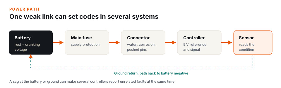
Controllers do not simply measure the battery posts. They measure the supply voltage at their own power input, after the main fuse, the harness, the connectors, and the ground return. A controller can see a lower voltage than a meter at the battery because of resistance in that path. The controller’s supply reading is the value that matters to its own logic.
A supply event can be a low voltage, a high voltage, or a voltage that moves quickly enough to reset a controller. The table may use the same system-voltage entry for more than one of those conditions, with the FMI distinguishing the direction or the type of fault. The label is the controller’s description, not a measurement you can read from the page.
Why controllers monitor their own supply
A controller needs a stable supply to run its processor, drive its outputs, and read its sensors. Many sensors use a reference voltage supplied by the controller, often around 5 volts. If the controller’s supply drops, the reference can drop with it, and the sensor signal can look implausible even when the sensor is working.
Controllers also protect their outputs. A driver that commands a relay, a pump, or a motor may shut down or report a fault when the supply is outside its expected range. The resulting code can name the output circuit rather than the supply, which is why a voltage event can produce entries that look like separate component failures.
The controller may also reset during a voltage dip. A reset can interrupt a communication message, clear a learned value, or cause the controller to log a memory or communication entry. Those entries are collateral observations. They describe what the controller experienced during the reset, not necessarily a failed module.
Code families that commonly cluster
The exact code set depends on the model and the table, but several families appear repeatedly in the published Polaris pages. The list below groups them by the system label. It is a reading guide, not a ranking of causes.
System voltage: SPN 168
The system-voltage entry is the most direct supply label in the table. It describes a supply that is high or low at the controller. When it appears with other entries, it is evidence that the controller recorded a supply condition during the same period. It is not proof that the supply caused every other entry, and its absence is not proof that the supply is good.
Relay and driver circuits
Chassis relay, fan relay, fuel pump driver, starter enable, and accessory relay entries are all outputs that depend on a stable supply. A relay coil that does not receive enough voltage can chatter or fail to pull in, and the controller may report a driver fault. The label names the output circuit; it does not prove that the relay or the pump is defective.
Electric power steering
Electric power steering and electric power-assisted steering draw significant current. The steering-assist entries in the SPN 520221 through 520231 range can appear with a supply event because the system is voltage-sensitive. A heavy-steering symptom with a steering-assist code and a system-voltage code is a different pattern from a steering-assist code alone.
Throttle and sensor plausibility
A reference voltage that moves outside its expected range can make a throttle, temperature, or pressure signal look implausible. The sensor may be working correctly while the reference it depends on is not. The table may record a throttle plausibility entry, a sensor circuit entry, or both.
Communication and controller memory
A controller that resets during a voltage dip can log a communication or memory entry. The entry may name a message, a module, or a calibration. It describes what the controller experienced, not necessarily a failed communication bus. The other entries in the cluster often provide the context.
Why the table shows unrelated systems
Polaris tables are organized by code, not by cause. A row for a fan relay and a row for a steering-assist circuit sit in the same table because they are both diagnostic entries the controller can publish. The table does not say that they share a supply, a ground, or a harness run. That connection is part of the machine’s electrical architecture, not the code list.
A shared table can also cover several models. The 83-entry table used by the 2022 Ranger 1000, the Sportsman 850 / XP 1000, the Scrambler XP 1000 S, and the Ranger SP 570 includes rows for systems that are not fitted to every machine. A cluster on one machine may include a row that is present in the table but not relevant to that build.
This is why the model-year page matters. The code on the display selects the row; the model notes identify the systems that are associated with the machine. The table supplies the label, and the source chapter supplies the definition.
Reading a cluster
A cluster is more useful when you record the entries together. The following details turn a list of codes into a pattern that can be compared with the table:
- Which codes appeared first. A supply entry that appears before the other entries is a different observation from one that appears after them.
- Which state each code was in. Active, stored, and history entries describe different moments. A stored code may have set during a previous key cycle.
- Whether the FMIs share a pattern. Several low-voltage or open-circuit FMIs in different systems can be consistent with a shared supply event. Several unrelated FMIs may not be.
- Whether a system-voltage row is present. The row is evidence, not a verdict, but it is part of the pattern.
- Whether the codes span more than one controller. Entries in different controllers can point to a shared supply or network; entries in one controller can point to a circuit within that controller’s harness.
- What was happening at the time. Cold start, winch use, plow operation, a water crossing, or a long idle with accessories on are different load conditions.
Record the state, not just the number
The same code can be active, stored, or history. The state is part of the observation. A history code with no current symptom is not the same as an active code that returns under load.
The ground return path
Every circuit needs a return path to the battery negative. On a powersports machine, that path can include the frame, the engine, a ground strap, and several connectors. Resistance in the return path raises the voltage the controller sees at its ground pin, which can make the supply look lower than it is.
A ground path is not a single wire. A controller may have a dedicated ground, a sensor may return through the controller, and a relay may ground through the chassis. A problem in one shared ground can affect several circuits that appear unrelated in the table. The voltage-path diagram shows the concept; the machine’s wiring diagram shows the actual grounds for your model.
The index does not publish a ground cleaning or tightening procedure. The OEM manual is the source for the ground locations, the fastener specifications, and the test points for your machine.
Connectors, water, and vibration
Powersports machines operate in water, mud, dust, and vibration. A connector that looks seated can have a pushed pin, a swollen seal, or corrosion inside the housing. A harness run can rub through an insulation layer where it passes a frame edge or a moving suspension component. These conditions can add resistance or create an intermittent connection that appears only under load or after a water crossing.
The table can name the circuit, but it cannot see the connector. A code that names a specific circuit is a reason to compare the label with the wiring diagram and the service information for the machine. The index does not provide a connector inspection procedure or a probe technique.
Dielectric grease, terminal condition, and connector repair are service topics. The cited OEM manual is the source for the correct materials and methods. A connector that is hot after a short run is a sign of resistance, but the index does not provide a procedure for evaluating it.
Winches, plows, and accessory loads
Accessories change the electrical picture. A winch, a plow actuator, a sound system, or an auxiliary light bar can draw more current than the charging system supplies at idle. The system voltage can sag, controllers can reset, and codes can appear. The codes may not occur during normal riding because the accessory is not running.
The table may show a system-voltage entry, a relay entry, or a driver entry depending on which controller recorded the event. The label describes the circuit the controller flagged. It does not tell you that the accessory is the cause, but the conditions you record can show the relationship. A cluster that appears only when the winch is running is a different observation from a cluster that appears on every cold start.
Accessory wiring is a service topic. The OEM manual and the accessory instructions are the sources for fusing, wire size, and connection points. The index does not provide installation guidance.
Cold weather and snowmobiles
Cold temperatures reduce the available cranking power of a lead-acid battery. Snowmobiles also deal with ice in connectors, snow intrusion, and heated-shield loads. A battery that is marginal in summer can produce a lower supply on a cold morning, and the resulting codes may disappear after the machine warms up.
The table cannot measure temperature or battery health. It can only show which circuits the controller flagged. A code that appears only on cold starts and clears after warm-up is a pattern worth recording, especially if the same code returns the next morning. The model-year page and the cited chapter provide the label; the service information provides the test procedure.
Jump-starting and charging are service topics. The owner’s manual is the source for the machine’s jump-start procedure and battery specification. The index does not provide a jump-start or charging procedure.
When the pattern is not the supply
A single circuit code that persists on a stable supply is a different pattern from a cluster. If one code names one connector and the other systems are quiet, the table is pointing at that circuit. The supply may still be involved, but the evidence is not a cluster.
A single code can also be a stored history entry from an earlier event. The state matters. A history code with no current symptom is a clue for the service record, not a reason to assume the circuit is failing now.
The index does not decide which pattern applies. It provides the labels, the states, and the source citation. The service information for the machine provides the tests that distinguish one circuit from another.
What to record with a voltage-related cluster
- Every code and every state. Record the SPN/FMI pair or P-code, and note whether it was active, stored, or history.
- The order of appearance. Note which code appeared first and which ones followed.
- The load conditions. Cold start, winch, plow, lights, audio, water, or a long idle with accessories on.
- The model year, model, and trim. The same cluster can map to different tables on different machines.
- The manual P/N and source chapter. The citation keeps the cluster attached to the correct model-year table.
What this guide does not cover
This guide does not provide a battery test, a charging-system test, a ground repair, a connector repair, or a jump-start procedure. It does not determine whether a machine is safe to operate. It explains why a supply event can produce a cluster of table entries and how to record those entries against the cited source.
For model-specific service information, use the OEM manual and the appropriate tools. The index is a code-label reference, not a repair guide.
Questions about voltage-related codes
Why do several unrelated codes appear at once?
A shared supply, a shared ground, a communication bus, or one voltage event can affect more than one controller. The table lists the entries; the pattern is built from the codes, states, and conditions you record.
Does a system-voltage code prove the battery is bad?
No. The code describes a supply condition at the controller. The battery, the charging system, the harness, the connectors, and the grounds are all part of that path. The code does not identify which one is responsible.
Can a low-voltage event set a throttle code?
Yes. A reference voltage that moves outside its expected range can make a throttle signal look implausible. The label describes the circuit condition, not a failed throttle assembly.
Why do the codes return after the battery is replaced?
A new battery changes one part of the supply path. It does not change the harness, the connectors, the grounds, or a circuit that has its own fault. The code may return if the original condition was not in the battery.
Does the index include charging-system codes?
The index includes the codes published in the cited owner’s manual chapters. Charging-system codes may appear on some models and not others. The model-year page and the source list show what is covered.
Where to look next
- Shared 83-code table — system voltage, relay, fan, throttle, AWD, and EPS entries for the 2022 Ranger 1000, Sportsman 850 / XP 1000, Scrambler XP 1000 S, and 2026 Ranger SP 570.
- Ranger 1000 / Crew 1000 (2023–2026) — the 78-entry table with voltage, fan, fuel-pump, and EPAS entries.
- RZR Pro R / Turbo R — the 302-entry condition table, including voltage and steering conditions.
- Fault-code decoder — search a cluster by code and model.
- Sources & data — how shared tables and model years are matched.
This guide is informational. It explains why supply-voltage events can produce code clusters and how to record them against the cited OEM table. It does not provide repair procedures or a diagnosis for a specific machine.