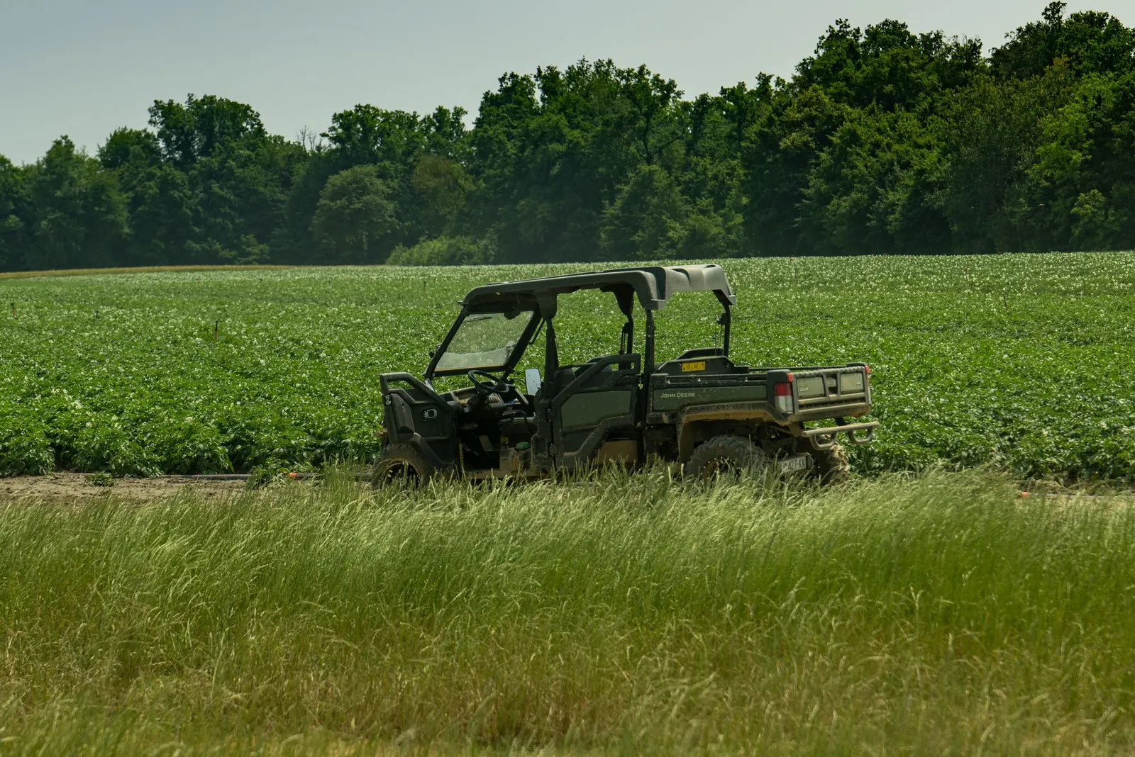
The diesel Ranger prints a compact, unchanging table
The Polaris Ranger Diesel reports diagnostics as SPN/FMI pairs from its diesel engine controller, and its owner’s manuals print exactly 32 diagnostic rows. The chapter is titled “Diagnostic Display Code Definitions”, and it is the controller’s complete owner-facing fault list. Where the EFI machines print 80, 200, or 300 rows, the diesel’s table is a third of a page.
The table is also fixed. The 2022, 2023, 2026, and 2027 Ranger Diesel manuals — covering the Tractor and MD/Israel editions published under manual part numbers 9940147, 9940850, 9941851, and 9942443, with the 2022 MD/Israel manual (P/N 9940146) printing the same table — all carry the identical 32 rows. This site publishes that table once, with a model-year anchor for each of the four primary editions, after a re-extraction confirmed the row sets are equal.
Its small size is not an accident. A diesel Ranger pairs a mechanical drivetrain with an electronic engine controller, and the owner-facing rows cover that controller’s diagnostic vocabulary — protection rows, driver rows, power and message rows. This guide explains how those rows are organized and how the diesel table differs from the EFI tables elsewhere on this site.
Components, conditions, and the FMI pattern
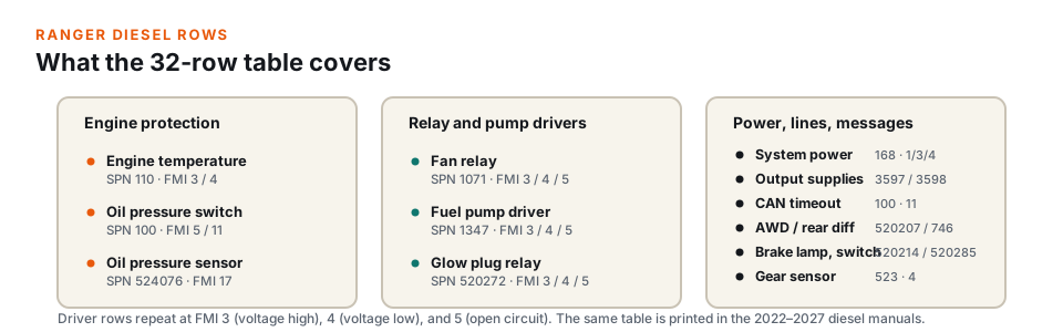
The diesel table is a component table: each row names the component, the condition the controller detected, and the SPN/FMI pair. The 32 rows organize into three groups. Engine protection contributes the engine temperature sensor (SPN 110 at FMI 3 and 4), the low oil pressure switch fault with two distinct conditions (SPN 100 at FMI 5 and FMI 11), and the oil pressure sensor (SPN 524076 at FMI 17). Relay and pump drivers each contribute three rows: the fan relay (1071), the fuel pump driver (1347), and the glow plug relay (520272). The remaining rows cover system power (SPN 168 at FMIs 1, 3, and 4), the controller output supply voltages (3597 and 3598), the CAN timeout fault, all-wheel drive control (520207), the brake failure lamp (520214) and brake switch (520285), the rear differential output (746), and the gear sensor signal (523).
The driver rows repeat a consistent three-step pattern: FMI 3 (voltage above normal), FMI 4 (voltage below normal), and FMI 5 (current below normal or open circuit). Ranking severity on this table means reading the FMI, not counting rows — the same component appears three times because the condition changes, not the circuit.
Glow plug rows and the cold-start indicator
The glow plug relay driver circuit contributes three of the 32 rows, at FMI 3, 4, and 5 — the same high / low / open pattern as the fan relay and the fuel pump. They are fault rows: each describes a problem detected on the relay’s driver circuit.
They are easy to confuse with the glow plug indicator, so the distinction matters. On the MD/Israel diesel manual, the indicator chapter describes the glow plug indicator illuminating while the glow plugs are active and turning off when the engine is ready to start — that is normal, by-design behavior during a cold start. The three table rows are the controller reporting a detected condition on the circuit that drives the relay. The indicator lighting on a cold morning and the display showing code 520272 are two different things, and a service record is clearer when it distinguishes them.
The CAN timeout row hides in plain sight
One row structure is easy to misread. The component named “Low oil pressure switch fault” appears twice with entirely different conditions: once as “current below normal or open circuit” (SPN 100, FMI 5) and once as “CAN message 65390 timeout error” (SPN 100, FMI 11). The second condition is a messaging fault — the controller stopped receiving the message in time — not an oil pressure reading at all.
This is why the diesel table rewards reading the condition column, not just the FMI number. Elsewhere on this site’s tables, SPN 100 with FMI 11 carries the same SAE meaning: abnormal communication failure. The diesel table simply places it under the component the missing message relates to. Anyone bookkeeping codes by SPN/FMI pair alone would file both rows under “oil pressure switch” and lose the distinction the table is making.
The system power rows carry the same lesson in the other direction. SPN 168 appears at FMI 1 (“data valid but below normal operational range — most severe level”), FMI 3, and FMI 4. A supply-voltage entry at the most severe level and a supply-voltage entry at a threshold level are different observations about the same input. The low-voltage guide on this site explains how system-power rows pattern with other entries in the same record.
Why the diesel table is short
The diesel controller’s owner-facing vocabulary is smaller than an EFI machine’s, and the manual reflects that. There is no P-code section here — the diesel table speaks entirely in SPN/FMI pairs — and there are no throttle-by-wire, pedal-position, or ignition-coil rows, because those systems are not part of this controller’s row vocabulary.
Short does not mean simple. Many of the 32 rows name circuits — relay drivers, output supplies, the rear differential output — that the owner’s manual assumes will be diagnosed with the machine’s wiring diagrams and the service information. The table supplies the label and the condition; the service information supplies the rest. The manuals also cover indicator behaviors outside the diagnostic table, such as the glow plug and park brake indicators, which is why this guide discusses them separately from the 32 rows.
Recording a diesel entry
The diesel table rewards complete records, and the details worth writing down are the ones that separate look-alike rows:
- The SPN and FMI pair. 520272-5 and 520272-3 name the same circuit at different conditions; the pair, not the component, is the row.
- The condition text. Especially on the switch rows, copy the condition string printed with the row — open-circuit and CAN-timeout readings on the same component are different evidence.
- The model year and manual P/N. The table is identical across editions, but the citation should still name the edition the row was compared against.
- Indicator state at the time. Whether the glow plug or low-oil indicator was on, and whether the engine had cooled or was at operating temperature, because indicator behavior and diagnostic rows are separate systems.
- The machine’s duty at the moment. Cold start, idle, accessory load, or transport says a lot about which drivers and supplies were energized when the row set.
A complete record like this travels well: it compares against the published table, against a previous service visit, and against another machine. Incomplete records — a code with no FMI or no condition text — tend to resurface as arguments about which entry was actually present.
Record the condition text with the code
On this table more than most, the same number repeats with different conditions. A service note that reads “520214” alone loses the difference between a circuit-high and a circuit-low brake-lamp entry. Copy the condition, the FMI, and the manual P/N — the citation is the evidence.
The four editions, one page
Because the four model years print the same table, this site publishes one page with a model-year anchor for each edition rather than four copies of the same rows. The page’s year navigation and records distinguish the 2022, 2023, 2026, and 2027 editions, and each anchor carries the source link to that manual’s chapter. If a user lands on an old per-year URL from previously, a redirect carries the table to the shared page and snaps to the matching anchor.
For anyone cross-referencing a used machine, the fixed table is convenient: a code on a 2023 means the same row as the same code on a 2027. It also means corrections apply to all four editions at once — when the source manuals revise the table, that is a site-wide correction, logged on the corrections page.
What this guide does not cover
This guide does not provide a no-start or hard-start procedure, a glow plug or battery service procedure, a fuel-system priming step, or a diagnosis for a specific machine. It does not list fuse or relay locations — the diagnostic table names circuits, and the machine’s wiring diagram and service information locate the components behind those names.
The manuals cover the diesel machine’s maintenance and operation chapters separately, including the indicator behaviors described above. If a row label looks wrong for a specific manual edition, the corrections page explains how to report it with the manual P/N and chapter.
Questions about Ranger Diesel codes
Are the 2026 and 2027 diesel tables the same as 2022?
Yes. The re-extraction behind the site’s table page confirmed the 32-row set is identical across the 2022, 2023, 2026, and 2027 manuals, and the page publishes one shared table with model-year anchors.
Why do some entries appear three times?
The driver rows repeat one component at three failure levels: FMI 3 (voltage high), FMI 4 (voltage low), and FMI 5 (open circuit). The component is the same; the detected condition changes.
What does the CAN timeout row mean if it mentions oil pressure?
The “Low oil pressure switch fault” component includes a condition of “CAN message 65390 timeout error” at FMI 11. That is a messaging fault observed on the message tied to that component, not an oil pressure reading.
Does the diesel table use P-codes?
No. The diesel table reports entirely as SPN/FMI pairs. P-codes appear on this site’s EFI and snowmobile table pages, not here.
Is the glow plug indicator lighting a fault?
No. Per the MD manual’s indicator chapter, the glow plug indicator illuminates while the glow plugs are active and turns off when the engine is ready to start. The three 520272 table rows are the fault conditions, not the indicator.
Where is the glow plug fuse in the table?
The table names the glow plug relay driver circuit (SPN 520272). Fuse and relay locations, ratings, and test points are wiring-diagram and service-information topics, outside the diagnostic table.
Where to look next
- Ranger Diesel fault codes (2022) — the published 32-row table; the page also anchors the 2023, 2026, and 2027 editions.
- How to read Polaris fault codes — the SPN/FMI format comparison and the FMI terminology glossary.
- Low-voltage Polaris codes — the system-power rows shared concept, and how supply events pattern across entries.
- Reading and clearing codes — active, stored, and history states, and what to record before anything is cleared.
- Codes by model year — how tables change or stay put between manual editions.
- Code decoder — decode an SPN/FMI pair at the console.
This guide is an independent reference prepared from the cited owner’s manuals. It is not affiliated with Polaris Inc., and the owner’s manuals remain the authoritative sources for the tables and the procedures.