
E-VES is the exhaust valve module, and the manuals keep its codes apart
On Polaris snowmobiles with the exhaust valve module, the owner’s manuals give the system its own diagnostic chapter. The shared DTC tables print a pointer — for all E-VES diagnostic trouble codes, see the E-VES diagnostic trouble codes chapter — and that referenced chapter publishes a separate 16-row table. This guide explains what the module is, how its three valve positions map to the letter-suffixed codes, and how the sixteen rows are organized.
The module is the exhaust valve’s electronic controller: an actuator inside the exhaust valve mechanism plus the converter that drives it. The manual’s chapter is titled “E-VES Diagnostic Trouble Codes (DTCs)”, and its table is different in kind from the machine P-code lists: the rows are module-specific and carry their own SPN and FMI values rather than the machine-wide format.
This guide describes the table and the system behavior the manuals publish. It does not provide a relearn procedure, a wiring repair procedure, or a diagnosis for a specific machine.
Three valve positions and one fallback state
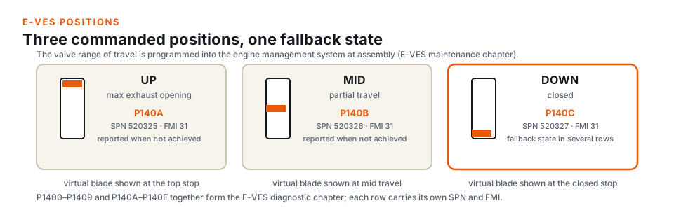
The exhaust valve moves through three commanded positions: UP for the open end of its travel, MID for partial travel, and DOWN for the closed position. The system’s range of travel is programmed into the engine management system at assembly, so the controller has a reference for what each position should look like — and the position codes are, in effect, the controller reporting that a learned position could not be achieved.
The three position rows sit at the end of the code series: P140A for the OPEN position not achieved, P140B for the MID position not achieved, and P140C for the DOWN position not achieved. The DOWN row is the important one for reading the overall table, because in the module’s diagnostic rows the closed state is the prevailing fallback when something in the chain goes wrong: several of the fault rows describe a controller response of forcing the valve to the DOWN state while fueling from the actual position.
The sixteen rows, grouped
The chapter’s sixteen rows all sit in the P140x series, including the letter-suffixed range. Organized by what they describe, the table reads as four groups:
- Diagnostic line conditions (SPN 520324). P1400 for diagnostic voltage too high, P1401 for the diagnostic circuit open or grounded, P1403 for a hardware fault, P1402 for a learn failure, P1404 for the commanded position not achieved, and P1405 for a missing PWM set signal. These six rows share one SPN and separate failure modes by FMI.
- Position feedback (SPN 520335). P1406 for the feedback position short to +12V, P1407 for the feedback position circuit open or grounded, and P1408 for an abnormal rate of change on the same circuit.
- Thermal, relay, and learn rows. P1409 is the actuator overheat row (SPN 520334), P140D and P140E are the EV relay rows (SPN 520328, open or grounded and short to power), and P1410 is the learn-default row (SPN 520337). P1410 is worth noting separately because a learn/default row is a system-recovery entry, not a circuit fault.
- Position achievement (SPN 520325, 520326, 520327). The P140A/P140B/P140C rows that report the OPEN, MID, and DOWN positions not being achieved.
The letter suffixes are not an afterthought — they are how the table extends past the nine numeric rows without renumbering codes that may already be referenced in service records. When comparing a display code to the table, read the suffix as part of the code; P1404 and P140A are different rows with different SPNs.
How a row reads beyond the label
The manual’s chapter pairs every code with its SPN, its FMI, the fault label, a likely cause, and the ECU’s response — and then a course-of-action column that belongs to service information. The site’s table page publishes the code, the SPN/FMI cross-reference, and a short label; the same page explains that the manual carries the cause and response text for each row.
Two response patterns are worth knowing at the reading level. Rows that cannot trust the valve’s position describe the controller fueling according to the actual position rather than the planned one — an explicitly degraded state rather than a shutdown. Rows that fail a position check describe the valve being forced toward the fallback state and the controller withholding the positions the fault prevents, such as not allowing the UP state. Neither pattern is published here as direction; describing it explains why an entry can appear while the engine still runs — the table labels faulted systems, not operating verdicts.
What the hardware is called in the rows
The module’s components pick up several names in the manual’s cause text, and knowing them makes the table far easier to read against a service notice. The actuator is described as the EV actuator — the position sensor and motor end of the exhaust valve assembly. The converter that drives it is described in the cause columns as the signal converter, the PWM converter being the same device in the E-VES chapter’s framing. The EV relay is the supply-side component the relay rows (P140D and P140E) name, and the EV cable is the mechanical cable that connects the actuator to the exhaust valve.
None of these names selects a row on their own; the P-code does. But when a mechanic, a forum post, or a parts listing names one of the components, the table owner can map the conversation to a row: the relay rows are P140D/P140E, the position rows are the P140A/B/C set, and the line rows sit in the numeric block. That mapping is exactly what the SPN column confirms — each component element lands on its own SPN.
Break-in can set these codes by design
The E-VES maintenance chapter in the owner’s manuals carries one note that prevents a common misreading: during engine break-in, E-VES diagnostic codes may appear during engine operation as the valves wear into their cylinder slots. The manuals add that the system is designed to work when oil and carbon deposits form on the valves — periodic valve inspection and cleaning is not required or recommended because the exhaust valves do not rely on combustion pressure for operation — and that if the check engine MIL remains illuminated after the break-in period, the manual directs the owner to an authorized Polaris dealer.
In other words, a stored E-VES entry early in a machine’s life is not automatically a wiring or actuator fault; the manual expects wear-in events and describes what the system does with them. For anyone reading a history record, the machine’s hours and the timing of the entry belong in the record along with the code. A P-code logged during the first tanks of fuel and an identical P-code logged after hours of duty are different observations. The index supplies the label; the record supplies the context.
Why one record covers several manuals
The 16-entry E-VES chapter is printed identically across several model-year manuals — the 2022 600 AXYS / PRO-RMK / RMK manuals and the 2023-2024 Patriot Boost manuals all carry the same table. This site publishes it once, citing the 2022 600 AXYS Indy SP / RMK manual (P/N 9940120), because the chapter is a shared component table rather than a per-model list. One code page gets one URL, and the source citation names which manual edition carried the chapter.
The maintenance chapter also sets the service boundary directly: E-VES service should be performed by an authorized Polaris dealer with the tools and diagnostic software to properly service and program the system. The relearn, the programming, and the adjustment steps are service information, and this guide does not publish them.
The main table’s exhaust-valve rows are a separate observation
The machine’s main DTC tables carry their own exhaust-valve SPN rows — the 600 AXYS gauge display-code table, for example, includes EV actuator and exhaust-valve entries. Those rows and the E-VES P-codes describe the same piece of hardware from two different chapters. If both appear in records, note which chapter each came from; the labels do not substitute for each other.
What this guide does not cover
This guide does not explain how to enter a diagnostic or service mode. It does not provide a relearn or learn procedure, an actuator or converter replacement procedure, wiring repair steps, or a diagnosis for a specific machine. The cited manuals cover those topics: the DTC chapter for row-level cause and response text, and the maintenance chapter for the service boundary. The site’s table page publishes the complete 16-row code list with SPN/FMI cross-references.
Engineering changes to the module are outside anything an owner’s manual describes. If a code label looks wrong for a specific manual, the corrections page explains how to report it with the manual P/N and chapter.
Questions about E-VES codes
What does E-VES stand for?
Electronic Variable Exhaust System — the manuals carry a chapter titled “Electronic Variable Exhaust System (E-VES) Maintenance” alongside the E-VES diagnostic chapter, and describe the hardware as the exhaust valve’s electronic controller: an actuator plus the PWM converter that drives it.
Why do I see a P-code instead of an SPN?
The DTC display on the machine reports the P-code. The chapter’s table pairs that P-code with SPN and FMI values, so both forms name the same row. Which form your records should carry depends on what the display or the service tool printed.
Are P1404 and P140A the same code?
No. P1404 (SPN 520324) reports the commanded position not achieved; P140A (SPN 520325) reports the OPEN position not achieved. The suffix selects a different row with its own SPN — and the manual’s P1404 row notes that it can also trigger one of the P140A/B/C position rows.
Is a P1410 entry a circuit fault?
No. P1410 is a learn-default row — a system-recovery entry. The circuit rows are the ones that describe voltage, open, or short conditions on named lines.
Can the codes appear during break-in?
Per the E-VES maintenance chapter, E-VES diagnostic codes may appear during engine break-in as the valves wear into their cylinder slots. The manual expects wear-in events; the record’s timing matters when reading them later.
Does this site publish the relearn procedure?
No. Relearn and programming steps are service procedures. The manuals themselves direct E-VES service to an authorized Polaris dealer with the required tools and diagnostic software.
Where to look next
- E-VES fault codes — the published 16-row table with each code’s SPN/FMI cross-reference and the source manual citation.
- 2022 600 AXYS display codes — the gauge display-code table, which includes its own exhaust-valve SPN rows.
- 2022 600 AXYS fault codes — the machine P-code list for the same manual’s main diagnostic chapter.
- 2022 Indy VR1 fault codes — P-code reporting on the next snowmobile platform over, with SPN/FMI cross-references.
- Polaris P-codes — how P-code families map to circuits and why the same P-code can mean different rows by model.
- How to read Polaris fault codes — SPN/FMI versus P-code format and the FMI terminology.
This guide is an independent reference prepared from the cited owner’s manuals. It is not affiliated with Polaris Inc., and the owner’s manuals remain the authoritative sources for the tables and the procedures.